RSS

Save all console logs by default in SecureCRT

Following parameters I am using for quite some time now in SecureCRT, the idea is to log every session I open with SecureCRT by default e.g. console, SSH or telnet. This is quite useful when you need to drill down to specific output on the devices you worked on weeks back.

SecureCRT-logging


Below parameter will save device connection type, its name (if configured) time and date.

D:\PATH\SecureCRT\Logs\ %H %S %h%m %D %M session.log

Below parameter will save device type, its name (if configured), connection/disconnection time and date within the file

===================== Connected to %H %S %m%h %D-%M=========================

=====================Disconnected from %H %S %m%h %D-%M ============

 
Leave a comment

Posted by on September 3, 2013 in Uncategorized


ClassFull Subnet in easy graphic image

imageimage


Benefits and limitations of VSLM

image


image

image


Juniper VPLS


VPLS Overview

Virtual private LAN service (VPLS) is an Ethernet-based point-to-multipoint Layer 2 VPN. It allows you to connect geographically dispersed Ethernet LAN sites to each other across an MPLS backbone. For customers who implement VPLS, all sites appear to be in the same Ethernet LAN even though traffic travels across the service provider’s network.

VPLS, in its implementation and configuration, has much in common with an MPLS Layer 2 VPN. In a VPLS topology, a packet originating within a customer’s network is sent first to a customer edge (CE) device (for example, a router or Ethernet switch). It is then sent to a provider edge (PE) router within the service provider’s network. The packet traverses the service provider’s network over an MPLS label-switched path (LSP). It arrives at the egress PE router, which then forwards the traffic to the CE device at the destination customer site.

The difference is that for VPLS, packets can traverse the service provider’s network in point-to-multipoint fashion, meaning that a packet originating from a CE device can be broadcast to all the PE routers participating in a VPLS routing instance. In contrast, a Layer 2 VPN forwards packets in point-to-point fashion only. The paths carrying VPLS traffic between each PE router participating in a routing instance are signaled using BGP.

This topic contains the following sections:

Sample VPLS Topology

Figure 6 shows a basic VPLS topology.

Figure 6: Basic VPLS Topology

Image g015524.gif

In this sample, the PE routers use the same autonomous system (AS). Within the AS, routing information is communicated through an interior gateway protocol (IGP). Outside the AS, routing information is shared with other ASs through BGP. The PE routers must use the same signaling protocols to communicate.

VPLS on PE Routers

Within a VPLS configuration, a device running JUNOS Software can act as a PE router. JUNOS Software passes the VPLS traffic through the following ports and PIMs on the Juniper Networks device to CE routers in the VPLS network:

  • Built-in Ethernet ports on front panel
  • Gigabit Ethernet uPIMs
  • Gigabit Ethernet ePIMs
  • Fast Ethernet PIMs
  • Fast Ethernet ePIMs

Note: Ports on uPIMs and ePIMs must be in routing mode before you can configure the corresponding interfaces for VPLS.

Because a VPLS carries Ethernet traffic across a service provider network, it must mimic an Ethernet network in some ways. When a PE router configured with a VPLS routing instance receives a packet from a CE device, it first determines whether it has the destination of the VPLS packet in the appropriate routing table. If it does, it forwards the packet to the appropriate PE router or CE device. If it does not, it broadcasts the packet to all other PE routers and CE devices that are members of that VPLS routing instance. In both cases, the CE device receiving the packet must be different from the one sending the packet.

When a PE router receives a packet from another PE router, it first determines whether it has the destination of the VPLS packet in the appropriate routing table. If it does, the PE router either forwards the packet or drops it depending on whether the destination is a local or remote CE device:

  • If the destination is a local CE device, the PE router forwards the packet to it.
  • If the destination is a remote CE device (connected to another PE router), the PE router discards the packet.

If the PE router cannot determine the destination of the VPLS packet, it floods the packet to all attached CE devices. Figure 7 illustrates this process.

Figure 7: Flooding a Packet with an Unknown Destination

Image g032400.gif

A VPLS can be directly connected to an Ethernet switch. Layer 2 information gathered by an Ethernet switch, for example, MAC addresses and interface ports, is included in the VPLS routing instance table.

An MPLS label-switched interface (LSI) label is used as the inner label for VPLS. This label maps to a VPLS routing instance. On the PE router, the LSI label is stripped and then mapped to a logical LSI interface. The Layer 2 Ethernet frame is then forwarded using the LSI interface to the correct VPLS routing instance.

One restriction on flooding behavior in VPLS is that traffic received from remote PE routers is never forwarded to other PE routers. This restriction helps prevent loops in the core network. However, if a CE Ethernet switch has two or more connections to the same PE router, you must enable the Spanning Tree Protocol (STP) on the CE switch to prevent loops.

Note: Under certain circumstances, VPLS PE routers might duplicate an Internet Control Message Protocol (ICMP) reply from a CE device when a PE router has to flood an ICMP request because the destination MAC address has not yet been learned. The duplicate ICMP reply can be triggered when a CE device with promiscuous mode enabled is connected to a PE router. The PE router automatically floods the promiscuous mode enabled CE device, which then returns the ICMP request to the VPLS PE routers. The VPLS PE routers consider the ICMP request to be new and flood the request again, creating a duplicate ping reply.

Using an Ethernet Switch as the VPLS CE Device

For VPLS configurations, the CE device does not necessarily need to be a router. You can link the PE routers directly to Ethernet switches. However, be aware of the following configuration issues:

  • When you configure VPLS routing instances and establish two or more connections between a CE Ethernet switch and a PE router, you must enable the Spanning Tree Protocol (STP) on the switch to prevent loops.
  • JUNOS Software allows standard bridge protocol data unit (BPDU) frames to pass through emulated Layer 2 connections, such as those configured with Layer 2 VPNs, Layer 2 circuits, and VPLS instances. However, CE Ethernet switches that generate proprietary BPDU frames might not be able to run STP across Juniper Networks routing platforms configured for these emulated Layer 2 connections.

VPLS Exceptions on J Series and SRX Series Devices

The VPLS implementation on a J Series or SRX Series device is similar to VPLS implementations on M Series, T Series, and MX Series routers, with the following exceptions:

  • J Series or SRX Series devices do not support aggregated Ethernet interfaces. Therefore, aggregated Ethernet interfaces between CE devices and PE routers are not supported for VPLS routing instances on J Series or SRX Series devices.
  • VPLS routing instances on J Series or SRX Series devices use BGP to send signals to other PE routers. LDP signaling is not supported.
  • VPLS multihoming, which allows connecting a CE device to multiple PE routers to provide redundant connectivity, is not supported on J Series or SRX Series devices.
  • J Series or SRX Series devices do not support BGP mesh groups.
  • J Series or SRX Series devices support only the following encapsulation types on VPLS interfaces that face CE devices: extended VLAN VPLS, Ethernet VPLS, and VLAN VPLS. Ethernet VPLS over ATM LLC encapsulation is not supported.
  • Virtual ports are generated dynamically on a Tunnel Services PIC on some Juniper Networks routing platforms. J Series or SRX Series devices do not support Tunnel Services modules or virtual ports.
  • The VPLS implementation on J Series or SRX Series devices does not support dual-tagged frames. Therefore, VLAN rewrite operations are not supported on dual-tagged frames. VLAN rewrite operations such as pop-pop, pop-swap, push-push, swap-push, and swap-swap, which are supported on M Series and T Series routing platforms, are not supported on J Series or SRX Series devices.
  • Firewall filters for VPLS are not supported.
Related Topics


Tags: , , , ,

Understanding Persistent NAT (SRX JUNOS)

Persistent NAT allows applications to use the Session Traversal Utilities for NAT (STUN) protocol when passing through NAT firewalls (see Understanding Session Traversal Utilities for NAT (STUN) Protocol). Persistent NAT ensures that all requests from the same internal transport address are mapped to the same reflexive transport address (the public IP address and port created by the NAT device closest to the STUN server).

The following types of persistent NAT can be configured on the Juniper Networks device:

  • Any remote host—All requests from a specific internal IP address and port are mapped to the same reflexive transport address. Any external host can send a packet to the internal host by sending the packet to the reflexive transport address.
  • Target host—All requests from a specific internal IP address and port are mapped to the same reflexive transport address. An external host can send a packet to an internal host by sending the packet to the reflexive transport address. The internal host must have previously sent a packet to the external host’s IP address.
  • Target host port—All requests from a specific internal IP address and port are mapped to the same reflexive transport address. An external host can send a packet to an internal host by sending the packet to the reflexive transport address. The internal host must have previously sent a packet to the external host’s IP address and port.

You configure any of the persistent NAT types with source NAT rules. The source NAT rule action can use a source NAT pool (with or without port translation) or an egress interface. Persistent NAT is not applicable for destination NAT, because persistent NAT bindings are based on outgoing sessions from internal to external.

Note: Port overloading is used in Junos OS only for normal interface NAT traffic. Persistent NAT does not support port overloading, and you must explicitly disable port overloading with the port-overloading off option at the [edit security nat source] hierarchy level.

To configure security policies to permit or deny persistent NAT traffic, you can use two new predefined services—junos-stun and junos-persistent-nat.

Note: Persistent NAT is different from the persistent address feature (see Understanding Persistent Addresses). The persistent address feature applies to address mappings for source NAT pools configured on the device. The persistent NAT feature applies to address mappings on an external NAT device, and is configured for a specific source NAT pool or egress interface. Also, persistent NAT is intended for use with STUN client/server applications.

Configuration Example — Persistent NAT

http://kb.juniper.net/InfoCenter/index?page=content&id=KB21296

 
Leave a comment

Posted by on October 30, 2011 in JUNOS Security, SRX Series


Tags: ,

Configuring VRRP in JUNOS : Example


Configure one master (Router A) and one backup (Router B) routing platform. The address configured in the virtual-address statements differs from the addresses configured in the address statements. When you configure multiple VRRP groups on an interface, you configure one to be the master virtual router for that group.

On Router A

[edit]

interfaces {

    ge-0/0/0 {

        unit 0 {

            family inet {

                address 192.168.1.20/24 {

                    vrrp-group 27 {

                        virtual-address 192.168.1.15;

                        priority 254;

                        authentication-type simple;

                        authentication-key booJUM;

                    }

                }

            }

        }

    }

}


On Router B


[edit]

interfaces {

    ge-4/2/0 {

        unit 0 {

            family inet {

                address 192.168.1.24/24 {

                    vrrp-group 27 {

                        virtual-address 192.168.1.15;

                        priority 200;

                        authentication-type simple;

                        authentication-key booJUM;

                    }

                }

            }

        }

    }

}


Configuring One Router to be the Master Virtual Router for the Group


[edit]

interfaces {

    ge-0/0/0 {

        unit 0 {

            family inet {

                address 192.168.1.20/24 {

                    vrrp-group 2 {

                        virtual-address 192.168.1.20;

                        priority 255;

                        advertise-interval 3;

                        preempt;

                    }

                   vrrp-group 10 {

                        virtual-address 192.168.1.55;

                        priority 201;

                        advertise-interval 3;

                    }

                    vrrp-group 1 {

                        virtual-address 192.168.1.54;

                        priority 22;

                        advertise-interval 4;

                    }

                }

            }

        }

    }

}


Configuring VRRP and MAC Source Address Filtering


The VRRP group number is the decimal equivalent of the last byte of the virtual MAC address.


[edit interfaces]

ge-5/2/0 {

    gigether-options {

        source-filtering;

        source-address-filter {

            00:00:5e:00:01:0a; # Virtual MAC address

        }

    }

    unit 0 {

        family inet {

            address 192.168.1.10/24 {

                vrrp-group 10 { # VRRP group number

                virtual-address 192.168.1.10;

                priority 255;

                preempt;

            }

        }

    }


Leave a comment

Posted by on October 25, 2011 in Routing Platform, Routing Protocol


Tags:

Understanding Logical Tunnel Interface (lt-0/0/0) on SRX


Summary:

This article provides information on the purpose and behavior of logical tunnel interfaces (lt-0/0/0), as well as how to configure and troubleshoot these interfaces on the SRX Series platforms.

Objective:

  • Need to form a logical connection between instances on the same Junos device and route between the connected instances.

Host 1 --> ge-0/0/1.0   ---SRX---  ge-0/0/2.0 <-- Host 2
Host 1 Network - 192.168.1.0/24, in routing-instance R1
Host 2 Network - 192.168.2.0/24, in routing-instance R2

  • Establish connectivity (using dynamic routing protocols) between these two hosts that are in two different routing-instances through a logical connection.

Solution:

Overview

In addition to sharing routes between instances, you can also form logical or physical connections between instances on the same Junos device and route between the connected instances.
To connect two routing instances with a logical connection, configure a logical tunnel interface for each instance. Then, configure a peer relationship between the logical tunnel interfaces, thus creating a point-to-point connection. To configure a point-to-point connection between two routing instances, configure the logical tunnel interface using the lt-fpc/pic/port format.
When configuring logical tunnel interfaces, note the following:

  • Configure each logical tunnel interface with one of the following encapsulation types: Ethernet, Ethernet circuit cross-connect (CCC), Ethernet Virtual Private LAN Service (VPLS), Frame Relay, Frame Relay CCC, Virtual LAN (VLAN), VLAN CCC, or VLAN VPLS.
  • Configure the IP, IPv6, International Organization for Standardization (ISO), or MPLS protocol family.
  • Configure only one peer unit for each logical interface. For example, unit 0 cannot peer with both unit 1 and unit 2.
  • To enable the logical tunnel interface, you must configure at least one physical interface statement.

In addition to logical tunnel interfaces, you can also use physical interfaces to connect and route between routing instances. This implementation method typically requires two physical ports, one for each instance.  Define the physical interfaces as you normally would and simply associate each interface with its respective routing instance under the [edit routing-instance instance-name] hierarchy.
If utilizing physical cables to connect instances, expect the session table to show two sessions. However, the same virtualization occurs with logical tunnels.


Setup

Host 1 --> ge-0/0/1.0 ---SRX--- ge-0/0/2.0 <-- Host 2
Where:
Host 1 Network – 192.168.1.0/24, in routing-instance R1
Host 2 Network – 192.168.2.0/24, in routing-instance R2
Add a logical unit in each of the routing-instance and configure peering between them to run dynamic routing protocol on this point-to-point connection.  This results in:
lt-0/0/0.1 in routing-instance R1
lt-0/0/0.2 in routing-instance R2
ge-0/0/1.0 and lt-0/0/0.1 are associated with security-zone Z1
ge-0/0/2.0 and lt-0/0/0.2 are associated with security-zone Z2


CLI Configuration


root@jtac# run show configuration | no-more 
## Last commit: 2011-06-17 05:03:28 UTC by root
version 10.2R3.10;
system {
    host-name jtac;
    root-authentication {
        encrypted-password "$1$kJ3WyE9V$9HA.Drh0Ws0z1cn9LB05A."; ## SECRET-DATA
    }
}
interfaces {
    lt-0/0/0 {
        unit 1 {
            encapsulation ethernet;
            peer-unit 2;
            family inet {
                address 10.20.30.1/30;
            }
        }
        unit 2 {
            encapsulation ethernet;
            peer-unit 1;
            family inet {
                address 10.20.30.2/30;
            }
        }
    }
    ge-0/0/1 {
        unit 0 {
            family inet {
                address 192.168.1.1/24;
            }
        }
    }
    ge-0/0/2 {
        unit 0 {
            family inet {
                address 192.168.2.1/24;
            }
        }
    }
}
policy-options {
    policy-statement p1 {
        from {
            instance R1;
            protocol direct;
        }
        then accept;
    }
    policy-statement p2 {
        from {
            instance R2;
            protocol direct;
        }
        then accept;
    }
}
security {
    zones {
        security-zone Z1 {
            host-inbound-traffic {
                system-services {
                    all;
                }
                protocols {
                    all;
                }
            }
            interfaces {
                ge-0/0/1.0;
                lt-0/0/0.1;
            }
        }
        security-zone Z2 {
            host-inbound-traffic {
                system-services {
                    all;
                }
                protocols {
                    all;
                }
            }
            interfaces {
                ge-0/0/2.0;
                lt-0/0/0.2;
            }
        }
    }
    policies {
        from-zone Z1 to-zone Z1 {
            policy Z1-Z1 {
                match {
                    source-address any;
                    destination-address any;
                    application any;
                }
                then {
                    permit;
                }
            }
        }
        from-zone Z2 to-zone Z2 {
            policy Z2-Z2 {
                match {
                    source-address any;
                    destination-address any;
                    application any;
                }
                then {
                    permit;
                }
            }
        }
    }
    flow {
        traceoptions {
            file lt-testing;
            flag basic-datapath;
            packet-filter 1 {
                source-prefix 192.168.1.2/32;
                destination-prefix 192.168.2.2/32;
            }
        }
    }
}
routing-instances {
    R1 {
        instance-type virtual-router;
        interface lt-0/0/0.1;
        interface ge-0/0/1.0;
        protocols {
            ospf {
                traceoptions {
                    file R1;
                    flag all;
                }
                export p1;
                area 0.0.0.0 {
                    interface lt-0/0/0.1;
                }
            }
        }
    }
    R2 {
        instance-type virtual-router;
        interface lt-0/0/0.2;
        interface ge-0/0/2.0;
        protocols {
            ospf {
                export p2;
                area 0.0.0.0 {
                    interface lt-0/0/0.2;
                }
            }
        }
    }
}

Verification

  1. Verify OSPF adjacency between two instances.  Use the show ospf neighbor command, as shown below:
    [edit]
    root@jtac# run show ospf neighbor instance R1 
    Address          Interface              State     ID               Pri  Dead
    10.20.30.2       lt-0/0/0.1             Full      10.20.30.2       128    34
    
    [edit]
    root@jtac# run show ospf neighbor instance R2    
    Address          Interface              State     ID               Pri  Dead
    10.20.30.1       lt-0/0/0.2             Full      10.20.30.1       128    36
  2. Verify the routing table in both instances.
    [edit]
    root@jtac# run show route 
    
    R1.inet.0: 6 destinations, 6 routes (6 active, 0 holddown, 0 hidden)
    + = Active Route, - = Last Active, * = Both
    
    10.20.30.0/30      *[Direct/0] 00:50:18
                        > via lt-0/0/0.1
    10.20.30.1/32      *[Local/0] 00:50:18
                          Local via lt-0/0/0.1
    192.168.1.0/24     *[Direct/0] 00:20:24
                        > via ge-0/0/1.0
    192.168.1.1/32     *[Local/0] 00:20:24
                          Local via ge-0/0/1.0
    192.168.2.0/24     *[OSPF/150] 00:43:29, metric 0, tag 0
                        > to 10.20.30.2 via lt-0/0/0.1
    224.0.0.5/32       *[OSPF/10] 00:56:36, metric 1
                          MultiRecv
    
    R2.inet.0: 6 destinations, 6 routes (6 active, 0 holddown, 0 hidden)
    + = Active Route, - = Last Active, * = Both
    
    10.20.30.0/30      *[Direct/0] 00:50:18
                        > via lt-0/0/0.2
    10.20.30.2/32      *[Local/0] 00:50:18
                          Local via lt-0/0/0.2
    192.168.1.0/24     *[OSPF/150] 00:20:24, metric 0, tag 0
                        > to 10.20.30.1 via lt-0/0/0.2
    192.168.2.0/24     *[Direct/0] 00:43:29
                        > via ge-0/0/2.0
    192.168.2.1/32     *[Local/0] 00:56:35
                          Local via ge-0/0/2.0
    224.0.0.5/32       *[OSPF/10] 00:56:36, metric 1
                          MultiRecv
    
  3. Check the session table.
    [edit]
    root@jtac# run show security flow session | no-more    
    Session ID: 793, Policy name: self-traffic-policy/1, Timeout: 52, Valid
      In: 10.20.30.1/1 --> 224.0.0.5/1;ospf, If: lt-0/0/0.2, Pkts: 375, Bytes: 25680
      Out: 224.0.0.5/1 --> 10.20.30.1/1;ospf, If: .local..4, Pkts: 0, Bytes: 0
    
    Session ID: 794, Policy name: self-traffic-policy/1, Timeout: 58, Valid
      In: 10.20.30.2/1 --> 224.0.0.5/1;ospf, If: lt-0/0/0.1, Pkts: 384, Bytes: 26280
      Out: 224.0.0.5/1 --> 10.20.30.2/1;ospf, If: .local..5, Pkts: 0, Bytes: 0
    
    Session ID: 2122, Policy name: Z1-Z1/5, Timeout: 2, Valid
      In: 192.168.1.2/17 --> 192.168.2.2/1;icmp, If: ge-0/0/1.0, Pkts: 1, Bytes: 60
      Out: 192.168.2.2/1 --> 192.168.1.2/17;icmp, If: lt-0/0/0.1, Pkts: 1, Bytes: 60
    
    Session ID: 2123, Policy name: Z2-Z2/6, Timeout: 2, Valid
      In: 192.168.1.2/17 --> 192.168.2.2/1;icmp, If: lt-0/0/0.2, Pkts: 1, Bytes: 60
      Out: 192.168.2.2/1 --> 192.168.1.2/17;icmp, If: ge-0/0/2.0, Pkts: 1, Bytes: 60
    Total sessions: 4


In the following example, a single ICMP packet is sent between hosts which are in two different routing instances, which transits an SRX device with a logical tunnel.  As expected, for this packet (ipid 60), session table shows two entries (IDs 2122 and 2123):

Jun 17 05:17:49 05:17:47.1931423:CID-0:RT:<192.168.1.2/17->192.168.2.2/1;1> matched filter 1:
Jun 17 05:17:49 05:17:47.1931423:CID-0:RT:packet [60] ipid = 297, @43ea261c
Jun 17 05:17:49 05:17:47.1931423:CID-0:RT:---- flow_process_pkt: (thd 6): flow_ctxt type 13, common flag 0x0, mbuf 0x43ea2480, 
rtbl_idx = 0
Jun 17 05:17:49 05:17:47.1931423:CID-0:RT: flow process pak fast ifl 72 in_ifp ge-0/0/1.0
Jun 17 05:17:49 05:17:47.1931423:CID-0:RT:  ge-0/0/1.0:192.168.1.2->192.168.2.2, icmp, (8/0)
Jun 17 05:17:49 05:17:47.1931423:CID-0:RT: find flow: table 0x5cec9ba8, hash 22784(0xffff), sa 192.168.1.2, da 192.168.2.2, sp 17, 
dp 1, proto 1, tok 394
Jun 17 05:17:49 05:17:47.1931925:CID-0:RT:  no session found, start first path. in_tunnel - 0, from_cp_flag - 0
Jun 17 05:17:49 05:17:47.1931925:CID-0:RT:self ip check: not for self (address=c0a80202)
Jun 17 05:17:49 05:17:47.1931925:CID-0:RT:  flow_first_create_session
Jun 17 05:17:49 05:17:47.1931925:CID-0:RT:  flow_first_in_dst_nat: in <ge-0/0/1.0>, out <N/A> dst_adr 192.168.2.2, sp 17, dp 1
Jun 17 05:17:49 05:17:47.1931925:CID-0:RT:  chose interface ge-0/0/1.0 as incoming nat if.
Jun 17 05:17:49 05:17:47.1931925:CID-0:RT:flow_first_rule_dst_xlate: DST no-xlate: 0.0.0.0(0) to 192.168.2.2(1)
Jun 17 05:17:49 05:17:47.1931925:CID-0:RT:flow_first_routing: call flow_route_lookup(): src_ip 192.168.1.2, x_dst_ip 192.168.2.2, 
in ifp ge-0/0/1.0, out ifp N/A sp 17, dp 1, ip_proto 1, tos 0
Jun 17 05:17:49 05:17:47.1931925:CID-0:RT:Doing DESTINATION addr route-lookup
Jun 17 05:17:49 05:17:47.1931925:CID-0:RT:  routed (x_dst_ip 192.168.2.2) from Z1 (ge-0/0/1.0 in 0) to lt-0/0/0.1, 
Next-hop: 10.20.30.2
Jun 17 05:17:49 05:17:47.1931925:CID-0:RT:  policy search from zone Z1-> zone Z1 (0x0,0x110001,0x1)
Jun 17 05:17:49 05:17:47.1931925:CID-0:RT:  app 0, timeout 60s, curr ageout 60s
Jun 17 05:17:49 05:17:47.1931925:CID-0:RT:flow_first_src_xlate: 192.168.1.2/17 -> 192.168.2.2/1 | 192.168.2.2/1 -> 
0.0.0.0/17: nat_src_xlated: False, nat_src_xlate_failed: False
Jun 17 05:17:49 05:17:47.1931925:CID-0:RT:flow_first_src_xlate: src nat 0.0.0.0(17) to 192.168.2.2(1) returns status: 0, 
rule/pool id: 0/0, pst_nat: False.
Jun 17 05:17:49 05:17:47.1931925:CID-0:RT:  dip id = 0/0, 192.168.1.2/17->192.168.1.2/17
Jun 17 05:17:49 05:17:47.1931925:CID-0:RT:  choose interface lt-0/0/0.1 as outgoing phy if
Jun 17 05:17:49 05:17:47.1931925:CID-0:RT:is_loop_pak: No loop: on ifp: lt-0/0/0.1, addr: 192.168.2.2, rtt_idx:5
Jun 17 05:17:49 05:17:47.1931925:CID-0:RT:jsf sess interest check. regd plugins 10
Jun 17 05:17:49 05:17:47.1931925:CID-0:RT: Allocating plugin info block for 12 plugin(s) from OL
Jun 17 05:17:49 05:17:47.1931925:CID-0:RT:-jsf int check: plugin id  1, svc_req 0x0. rc 4
Jun 17 05:17:49 05:17:47.1931925:CID-0:RT:-jsf int check: plugin id  2, svc_req 0x2. rc 4
Jun 17 05:17:49 05:17:47.1931925:CID-0:RT:-jsf int check: plugin id  3, svc_req 0x0. rc 4
Jun 17 05:17:49 05:17:47.1931925:CID-0:RT:-jsf int check: plugin id  5, svc_req 0x0. rc 4
Jun 17 05:17:49 05:17:47.1931925:CID-0:RT:-jsf int check: plugin id  6, svc_req 0x0. rc 4
Jun 17 05:17:49 05:17:47.1931925:CID-0:RT:-jsf int check: plugin id  7, svc_req 0x0. rc 4
Jun 17 05:17:49 05:17:47.1931925:CID-0:RT:-jsf int check: plugin id  9, svc_req 0x0. rc 4
Jun 17 05:17:49 05:17:47.1931925:CID-0:RT:-jsf int check: plugin id 10, svc_req 0x0. rc 2
Jun 17 05:17:49 05:17:47.1931925:CID-0:RT: No JSF plugins enabled for session
Jun 17 05:17:49 05:17:47.1931925:CID-0:RT: Releasing plugin info block for 12 plugin(s) to OL
Jun 17 05:17:49 05:17:47.1931925:CID-0:RT:flow_first_service_lookup(): natp(0x5e8ad9b8): app_id, 0(0).
Jun 17 05:17:49 05:17:47.1931925:CID-0:RT:  service lookup identified service 0.
Jun 17 05:17:49 05:17:47.1931925:CID-0:RT:  flow_first_final_check: in <ge-0/0/1.0>, out <lt-0/0/0.1>
Jun 17 05:17:49 05:17:47.1931925:CID-0:RT:  existing vector list 200-51ab6360.
Jun 17 05:17:49 05:17:47.1931925:CID-0:RT:  Session (id:2122) created for first pak 200
Jun 17 05:17:49 05:17:47.1931925:CID-0:RT:  flow_first_install_session======> 0x5e8ad9b8
Jun 17 05:17:49 05:17:47.1931925:CID-0:RT: nsp 0x5e8ad9b8, nsp2 0x5e8ada1c
Jun 17 05:17:49 05:17:47.1932426:CID-0:RT:  make_nsp_ready_no_resolve()
Jun 17 05:17:49 05:17:47.1932426:CID-0:RT:  route lookup: dest-ip 192.168.1.2 orig ifp ge-0/0/1.0 output_ifp ge-0/0/1.0 
orig-zone 6 out-zone 6 vsd 0
Jun 17 05:17:49 05:17:47.1932426:CID-0:RT:  route to 192.168.1.2
Jun 17 05:17:49 05:17:47.1932426:CID-0:RT:Doing jsf sess create notify
Jun 17 05:17:49 05:17:47.1932426:CID-0:RT:Installing c2s NP session wing
Jun 17 05:17:49 05:17:47.1932426:CID-0:RT:Installing s2c NP session wing
Jun 17 05:17:49 05:17:47.1932426:CID-0:RT:  flow got session.
Jun 17 05:17:49 05:17:47.1932426:CID-0:RT:  flow session id 2122
Jun 17 05:17:49 05:17:47.1932426:CID-0:RT:mbuf 0x43ea2480, exit nh 0x60010
Jun 17 05:17:49 05:17:47.1932426:CID-0:RT: ----- flow_process_pkt rc 0x0 (fp rc 0)
Jun 17 05:17:49 05:17:47.1932426:CID-0:RT:<192.168.1.2/17->192.168.2.2/1;1> matched filter 1:
Jun 17 05:17:49 05:17:47.1932426:CID-0:RT:packet [60] ipid = 297, @43ea261c
Jun 17 05:17:49 05:17:47.1932426:CID-0:RT:---- flow_process_pkt: (thd 6): flow_ctxt type 0, common flag 0x0, mbuf 0x43ea2480, 
rtbl_idx = 0
Jun 17 05:17:49 05:17:47.1932426:CID-0:RT: flow_process_pkt_exception mbuf 43ea2480, ifd=75, ctxt_type=0, in_ifp <Z2:lt-0/0/0.2>
Jun 17 05:17:49 05:17:47.1932426:CID-0:RT:  lt-0/0/0.2:192.168.1.2->192.168.2.2, icmp, (8/0)
Jun 17 05:17:49 05:17:47.1932426:CID-0:RT: find flow: table 0x5cec9ba8, hash 22784(0xffff), sa 192.168.1.2, da 192.168.2.2, 
sp 17, dp 1, proto 1, tok 520
Jun 17 05:17:49 05:17:47.1932426:CID-0:RT:  no session found, start first path. in_tunnel - 0, from_cp_flag - 0
Jun 17 05:17:49 05:17:47.1932426:CID-0:RT:self ip check: not for self (address=c0a80202)
Jun 17 05:17:49 05:17:47.1932426:CID-0:RT:  flow_first_create_session
Jun 17 05:17:49 05:17:47.1932426:CID-0:RT:  flow_first_in_dst_nat: in <lt-0/0/0.2>, out <N/A> dst_adr 192.168.2.2, sp 17, dp 1
Jun 17 05:17:49 05:17:47.1932426:CID-0:RT:  chose interface lt-0/0/0.2 as incoming nat if.
Jun 17 05:17:49 05:17:47.1932426:CID-0:RT:flow_first_rule_dst_xlate: DST no-xlate: 0.0.0.0(0) to 192.168.2.2(1)
Jun 17 05:17:49 05:17:47.1932426:CID-0:RT:flow_first_routing: call flow_route_lookup(): src_ip 192.168.1.2, x_dst_ip 192.168.2.2, 
in ifp lt-0/0/0.2, out ifp N/A sp 17, dp 1, ip_proto 1, tos 0
Jun 17 05:17:49 05:17:47.1932426:CID-0:RT:Doing DESTINATION addr route-lookup
Jun 17 05:17:49 05:17:47.1932426:CID-0:RT:  routed (x_dst_ip 192.168.2.2) from Z2 (lt-0/0/0.2 in 0) to ge-0/0/2.0, 
Next-hop: 192.168.2.2
Jun 17 05:17:49 05:17:47.1932426:CID-0:RT:  policy search from zone Z2-> zone Z2 (0x0,0x110001,0x1)
Jun 17 05:17:49 05:17:47.1932426:CID-0:RT:  app 0, timeout 60s, curr ageout 60s
Jun 17 05:17:49 05:17:47.1932426:CID-0:RT:flow_first_src_xlate: 192.168.1.2/17 -> 192.168.2.2/1 | 192.168.2.2/1 -> 0.0.0.0/17: 
nat_src_xlated: False, nat_src_xlate_failed: False
Jun 17 05:17:49 05:17:47.1932426:CID-0:RT:flow_first_src_xlate: src nat 0.0.0.0(17) to 192.168.2.2(1) returns status: 0, 
rule/pool id: 0/0, pst_nat: False.
Jun 17 05:17:49 05:17:47.1932426:CID-0:RT:  dip id = 0/0, 192.168.1.2/17->192.168.1.2/17
Jun 17 05:17:49 05:17:47.1932928:CID-0:RT:  choose interface ge-0/0/2.0 as outgoing phy if
Jun 17 05:17:49 05:17:47.1932928:CID-0:RT:is_loop_pak: No loop: on ifp: ge-0/0/2.0, addr: 192.168.2.2, rtt_idx:4
Jun 17 05:17:49 05:17:47.1932928:CID-0:RT:jsf sess interest check. regd plugins 10
Jun 17 05:17:49 05:17:47.1932928:CID-0:RT: Allocating plugin info block for 12 plugin(s) from OL
Jun 17 05:17:49 05:17:47.1932928:CID-0:RT:-jsf int check: plugin id  1, svc_req 0x0. rc 4
Jun 17 05:17:49 05:17:47.1932928:CID-0:RT:-jsf int check: plugin id  2, svc_req 0x2. rc 4
Jun 17 05:17:49 05:17:47.1932928:CID-0:RT:-jsf int check: plugin id  3, svc_req 0x0. rc 4
Jun 17 05:17:49 05:17:47.1932928:CID-0:RT:-jsf int check: plugin id  5, svc_req 0x0. rc 4
Jun 17 05:17:49 05:17:47.1932928:CID-0:RT:-jsf int check: plugin id  6, svc_req 0x0. rc 4
Jun 17 05:17:49 05:17:47.1932928:CID-0:RT:-jsf int check: plugin id  7, svc_req 0x0. rc 4
Jun 17 05:17:49 05:17:47.1932928:CID-0:RT:-jsf int check: plugin id  9, svc_req 0x0. rc 4
Jun 17 05:17:49 05:17:47.1932928:CID-0:RT:-jsf int check: plugin id 10, svc_req 0x0. rc 2
Jun 17 05:17:49 05:17:47.1932928:CID-0:RT: No JSF plugins enabled for session
Jun 17 05:17:49 05:17:47.1932928:CID-0:RT: Releasing plugin info block for 12 plugin(s) to OL
Jun 17 05:17:49 05:17:47.1932928:CID-0:RT:flow_first_service_lookup(): natp(0x5e8adb50): app_id, 0(0).
Jun 17 05:17:49 05:17:47.1932928:CID-0:RT:  service lookup identified service 0.
Jun 17 05:17:49 05:17:47.1932928:CID-0:RT:  flow_first_final_check: in <lt-0/0/0.2>, out <ge-0/0/2.0>
Jun 17 05:17:49 05:17:47.1932928:CID-0:RT:  existing vector list 200-51ab6360.
Jun 17 05:17:49 05:17:47.1932928:CID-0:RT:  Session (id:2123) created for first pak 200
Jun 17 05:17:49 05:17:47.1932928:CID-0:RT:  flow_first_install_session======> 0x5e8adb50
Jun 17 05:17:49 05:17:47.1932928:CID-0:RT: nsp 0x5e8adb50, nsp2 0x5e8adbb4
Jun 17 05:17:49 05:17:47.1932928:CID-0:RT:  make_nsp_ready_no_resolve()
Jun 17 05:17:49 05:17:47.1932928:CID-0:RT:  route lookup: dest-ip 192.168.1.2 orig ifp lt-0/0/0.2 output_ifp lt-0/0/0.2 
orig-zone 8 out-zone 8 vsd 0
Jun 17 05:17:49 05:17:47.1932928:CID-0:RT:  route to 10.20.30.1
Jun 17 05:17:49 05:17:47.1932928:CID-0:RT:Doing jsf sess create notify
Jun 17 05:17:49 05:17:47.1932928:CID-0:RT:Installing c2s NP session wing
Jun 17 05:17:49 05:17:47.1932928:CID-0:RT:Installing s2c NP session wing
Jun 17 05:17:49 05:17:47.1932928:CID-0:RT:  flow got session.
Jun 17 05:17:49 05:17:47.1932928:CID-0:RT:  flow session id 2123
Jun 17 05:17:49 05:17:47.1932928:CID-0:RT:mbuf 0x43ea2480, exit nh 0x70010
Jun 17 05:17:49 05:17:47.1932928:CID-0:RT: flow_exit: SZ 0 cached_session 0
Jun 17 05:17:49 05:17:47.1932928:CID-0:RT:flow_process_pkt_exception: Freeing lpak 59f7edc8 associated with mbuf 0x43ea2480
Jun 17 05:17:49 05:17:47.1932928:CID-0:RT: ----- flow_process_pkt rc 0x0 (fp rc 0)
 

Note: To establish communication (bidirectional) between two hosts which are in two separate security zones and routing instances, connected though a logical tunnel interface – the SRX does not require any inter-zone security policy, all that is needed is an intra-zone policy.
The logical tunnel interface, which acts as a termination point in the first instance and as an originating point in the second instance, is the reason for two entries in the session table for the same packet.

 
2 Comments

Posted by on October 14, 2011 in JUNOS Security, Routing Platform, SRX Series


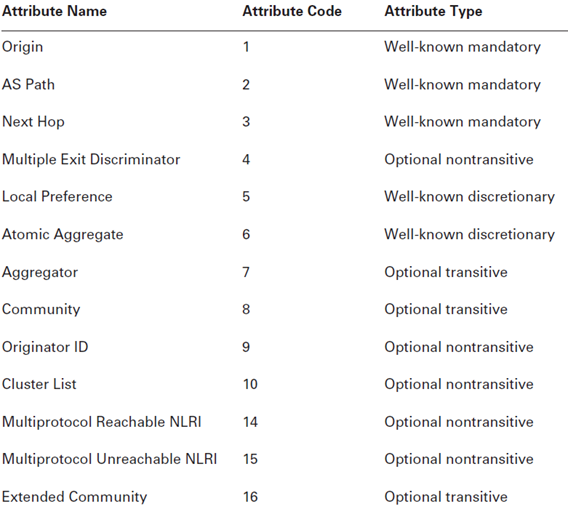
Common BGP Attributes

image


BGP Route selection

1. The router first verifies that a current route exists in the inet.0 routing table that provides reachability to the address specified by the Next Hop attribute. Should a valid route not exist, the path advertisement is not usable by the router and the route is marked as hidden in the routing table.

2. The router checks the Local Preference value and prefers all advertisements with the highest value. This is the only step in the algorithm that prefers a higher value over a lower value.

3. The router evaluates the length of the AS Path attribute. A shorter path length is preferred over a longer path length. When the attribute contains an AS Set segment, designated by the { and } braces, this set of values is considered to have a length of 1. For example, the AS Path of 65010 {65020 65030 65040} has a path length of 2.

4. The router checks the value in the Origin attribute. A lower Origin value is preferred over a higher value.

5. The router checks the value of the MED attribute for routes advertised from the same neighboring AS. A lower MED value is preferred over a higher MED value.

6. The router checks the type of BGP peer the path advertisement was learned from. Advertisements from EBGP peers are preferred over advertisements from IBGP peers.

7.The router determines the IGP metric cost to each BGP peer it received a path advertisement from. Advertisements from the peer with the lowest IGP cost are preferred. For all IBGP advertisements, the router also selects a physical next hop (or multiple next hops) for the advertisements from the lowest-cost peer. These physical next hops are selected using the following criteria:

              a. The router examines both the inet.0 and the inet.3 routing tables for the address of the BGP Next Hop. The physical next hop(s) associated with the lowest JUNOS software route preference is preferred. This often means that the router uses the inet.3 version of the next hop—a Multiprotocol Label Switching (MPLS)–label switched path.

                b. Should the preference values in the inet.0 and the inet.3 routing tables be equal, the router uses the physical next hop(s) of the instance in inet.3.

                 c. Should the preference values be identical and the routes be in the same routing table, inet.0   for example, the router evaluates the number of equal-cost paths of each route instance. The instance with the larger number of paths is preferred and its physical next hops are installed. This situation might occur when the default preference values are modified and the traffic-engineering bgp-igp MPLS configuration command is used.

8. The router determines the length of the Cluster List attribute. A shorter list length is preferred over a longer list length.

9. The router determines the router ID for each peer that advertised a path to the route destination.
                  a. Lower router ID value is preferred over a higher router ID value.

10. The router determines the peer ID for each peer that advertised a path to the router destination.
                  a. Lower peer ID value is preferred over a higher peer ID value. The peer ID is the IP address of the established BGP peering session.

image

 
Leave a comment

Posted by on September 30, 2011 in Routing Protocol


Tags: ,

HA Features on Juniper Networks Routing Platforms

Routing Engine Redundancy
Redundant Routing Engines are two Routing Engines that are installed in the same routing platform. One functions as the master, while the other stands by as a backup should the master Routing Engine fail. On routing platforms with dual Routing Engines, network re-convergence takes place more quickly than on routing platforms with a single Routing Engine.

Graceful Routing Engine Switchover

Graceful Routing Engine switchover (GRES) enables a routing platform with redundant Routing Engines to continue forwarding packets, even if one Routing Engine fails. Graceful Routing Engine switchover preserves interface and kernel information. Traffic is not interrupted. However, graceful Routing Engine switchover does not preserve the control plane. Neighboring routers detect that the router has experienced a restart and react to the event in a manner prescribed by individual routing protocol specifications. To preserve routing during a switchover, graceful Routing Engine switchover must be combined with either graceful restart protocol extensions or nonstop active routing. For more information, see Graceful Routing Engine Switchover Overview.

Nonstop Bridging

Nonstop bridging enables a routing platform with redundant Routing Engines to switch from a primary Routing Engine to a backup Routing Engine without losing Layer 2 Control Protocol (L2CP) information. Nonstop bridging uses the same infrastructure as graceful Routing Engine switchover to preserve interface and kernel information. However, nonstop bridging also saves L2CP information by running the Layer 2 Control Protocol process (l2cpd) on the backup Routing Engine.

Nonstop Active Routing

Nonstop active routing (NSR) enables a routing platform with redundant Routing Engines to switch from a primary Routing Engine to a backup Routing Engine without alerting peer nodes that a change has occurred. Nonstop active routing uses the same infrastructure as graceful Routing Engine switchover to preserve interface and kernel information. However, nonstop active routing also preserves routing information and protocol sessions by running the routing protocol process (rpd) on both Routing Engines. In addition, nonstop active routing preserves TCP connections maintained in the kernel.

Note: To use nonstop active routing, you must also configure graceful Routing Engine switchover.

Graceful Restart

With routing protocols, any service interruption requires an affected router to recalculate adjacencies with neighboring routers, restore routing table entries, and update other protocol-specific information. An unprotected restart of a router can result in forwarding delays, route flapping, wait times stemming from protocol reconvergence, and even dropped packets. To alleviate this situation, graceful restart provides extensions to routing protocols. These protocol extensions define two roles for a router—restarting and helper. The extensions signal neighboring routers about a router undergoing a restart and prevent the neighbors from propagating the change in state to the network during a graceful restart wait interval. The main benefits of graceful restart are uninterrupted packet forwarding and temporary suppression of all routing protocol updates. Graceful restart enables a router to pass through intermediate convergence states that are hidden from the rest of the network.

When a router is running graceful restart and the router stops sending and replying to protocol liveness messages (hellos), the adjacencies assume a graceful restart and begin running a timer to monitor the restarting router. During this interval, helper routers do not process an adjacency change for the router that they assume is restarting, but continue active routing with the rest of the network. The helper routers assume that the router can continue stateful forwarding based on the last preserved routing state during the restart.

If the router was actually restarting and is back up before the graceful timer period expires in all of the helper routers, the helper routers provide the router with the routing table, topology table, or label table (depending on the protocol), exit the graceful period, and return to normal network routing.

If the router does not complete its negotiation with helper routers before the graceful timer period expires in all of the helper routers, the helper routers process the router’s change in state and send routing updates, so that convergence occurs across the network. If a helper router detects a link failure from the router, the topology change causes the helper router to exit the graceful wait period and to send routing updates, so that network convergence occurs.

To enable a router to undergo a graceful restart, you must include the graceful-restart statement at either the global [edit routing-options] hierarchy level or the hierarchy level for a specific protocol. When a routing session is started, a router that is configured with graceful restart must negotiate with its neighbors to support it when it undergoes a graceful restart. A neighboring router will accept the negotiation and support helper mode without requiring graceful restart to be configured on the neighboring router.

Note: A Routing Engine switchover event on a helper router that is in graceful wait state causes the router to drop the wait state and to propagate the adjacency’s state change to the network.

Graceful restart is supported for the following protocols and applications:

  • BGP
  • ES-IS
  • IS-IS
  • OSPF/OSPFv3
  • PIM sparse mode
  • RIP/RIPng
  • MPLS-related protocols, including:
    • Label Distribution Protocol (LDP)
    • Resource Reservation Protocol (RSVP)
    • Circuit cross-connect (CCC)
    • Translational cross-connect (TCC)
  • Layer 2 and Layer 3 virtual private networks (VPNs)

For more information, see Graceful Restart Overview.

Nonstop Active Routing Versus Graceful Restart

Nonstop active routing and graceful restart are two different methods of maintaining high availability. Graceful restart requires a restart process. A router undergoing a graceful restart relies on its neighbors (or helpers) to restore its routing protocol information. The restart is the mechanism by which helpers are signaled to exit the wait interval and start providing routing information to the restarting router.

In contrast, nonstop active routing does not involve a router restart. Both the master and standby Routing Engines are running the routing protocol process (rpd) and exchanging updates with neighbors. When one Routing Engine fails, the router simply switches to the active Routing Engine to exchange routing information with neighbors. Because of these feature differences, nonstop routing and graceful restart are mutually exclusive. Nonstop active routing cannot be enabled when the router is configured as a graceful restarting router. If you include the graceful-restart statement at any hierarchy level and the nonstop-routing statement at the [edit routing-options] hierarchy level and try to commit the configuration, the commit request fails.

Effects of a Routing Engine Switchover

Understanding Graceful Routing Engine Switchover in the JUNOS Software describes the effects of a Routing Engine switchover when no high availability features are enabled and when graceful Routing Engine switchover, graceful restart, and nonstop active routing features are enabled.

VRRP

For Ethernet, Fast Ethernet, Gigabit Ethernet, 10-Gigabit Ethernet, and logical interfaces, you can configure the Virtual Router Redundancy Protocol (VRRP) or VRRP for IPv6. VRRP enables hosts on a LAN to make use of redundant routing platforms on that LAN without requiring more than the static configuration of a single default route on the hosts. The VRRP routing platforms share the IP address corresponding to the default route configured on the hosts. At any time, one of the VRRP routing platforms is the master (active) and the others are backups. If the master fails, one of the backup routers becomes the new master router, providing a virtual default routing platform and allowing traffic on the LAN to be routed without relying on a single routing platform. Using VRRP, a backup router can take over a failed default router within a few seconds. This is done with minimum VRRP traffic and without any interaction with the hosts.

Routers running VRRP dynamically elect master and backup routers. You can also force assignment of master and backup routers using priorities from 1 through 255, with 255 being the highest priority. In VRRP operation, the default master router sends advertisements to backup routers at regular intervals. The default interval is 1 second. If a backup router does not receive an advertisement for a set period, the backup router with the next highest priority takes over as master and begins forwarding packets.

For more information, see Understanding VRRP.

Unified ISSU

A unified in-service software upgrade (unified ISSU) enables you to upgrade between two different JUNOS Software releases with no disruption on the control plane and with minimal disruption of traffic. Unified ISSU is only supported by dual Routing Engine platforms. In addition, graceful Routing Engine switchover (GRES) and nonstop active routing (NSR) must be enabled.

With a unified ISSU, you can eliminate network downtime, reduce operating costs, and deliver higher services levels. For more information, see Unified ISSU Overview.

 
Leave a comment

Posted by on September 30, 2011 in Routing Platform


Tags: , , , , ,

Default Route Policy of BGP, RIP, OSPF & IS-IS

Border Gateway Protocol (BGP)

BGP is the routing protocol of the Internet and connects different Autonomous Systems (ASs) together. The protocol supports the mesh-like interconnection structure of the ISPs that comprise the Internet backbone. BGP is a very policy-driven protocol that gives you control over exactly what routes are received and sent to a peer. Now let’s look at how the protocol is designed to work by default.

When a BGP router receives routes from a peer, it is designed to accept all of the routes advertised to it. The router performs this function for each peer it is currently communicating with. Once the routes are stored in memory, the router selects the best path to each distinct network and installs those in the forwarding table. These best paths (active BGP routes in inet.0) are then advertised to its BGP peers. The specific routes advertised to each peer will depend on the local router’s relationship with its peer. If the relationship is an internal one (both of the routers are in the same AS), then only routes originally received from an external peer will be advertised. The routes sent to an external peer are quite different, however. In this case, all active BGP routes will be sent to the external peer.

The default BGP import and export policies mirror this normal operation of BGP. The following summarizes these policies:

Import Policy (All Peers) A BGP router will accept all non-looped BGP routes received from another BGP router.
Export Policy (External Peers) A BGP router will advertise all active BGP routes in inet.0 to all configured external BGP peers.
Export Policy (Internal Peers) A BGP router will advertise all active BGP routes in inet.0 to all internal peers if the routes were originally received from an external peer.

Routing Information Protocol (RIP)

The default import and export policies for the JUNOS software implementation of RIP do not follow a “normal” operation of a distance-vector protocol. The default import policy is to accept all routes advertised to the local router via RIP. The default export policy for RIP is to not advertise any routes to any neighbors. One main reason for this seemingly odd behavior is that a Juniper Networks router is designed to run in the core of the Internet and RIP is not well suited for that use. However, many customer implementations need to receive RIP routes in their networks from server farms or remote access servers. These routes would then be advertised to the rest of the network using a different routing protocol. The JUNOS software
defaults for RIP support this functionality.

Open Shortest Path First (OSPF)

OSPF is a link-state routing protocol that mandates that each router in an OSPF area maintain an identical link-state database. Filtering out and rejecting incoming routing information could break this mandate, so import policies are not permitted. This means that there is no default import policy for OSPF.

The default export policy for OSPF is to reject all routes. While this sounds very similar to the default RIP export operation, things are actually quite different. OSPF advertises routing information in a format called a link-state advertisement (LSA). These LSAs contain the local
router’s networks and are generated by the protocol based on the current router configuration for OSPF and not on the routing table. In addition, these LSAs are flooded by the protocol on all operational OSPF interfaces. In this manner, all routers in the network receive a copy of each router’s information without ever consulting the routing table.

Intermediate System to Intermediate System (IS-IS)

Like OSPF, IS-IS is a link-state routing protocol. It also must maintain an identical link-state database on all routers in an IS-IS level. This once again means that import policies are not permitted and that there is no default import policy for IS-IS.

Route advertisements are also very similar to OSPF in that information is flooded throughout the network using an update packet called a link-state PDU (LSP). These LSPs are flooded throughout the network to all IS-IS routers using operational IS-IS interfaces. The difference
with IS-IS, however, is how the local router populates its own LSP. In OSPF, this was accomplished via the router’s configuration. For IS-IS, this information is actually retrieved from the routing table. To accommodate this difference, the default export policy for IS-IS is to export all direct routes configured for IS-IS.

Link-State IGP Policy Application

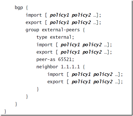
Policies are applied to both OSPF and IS-IS in an export fashion only. This follows the discussion in the “Default Policy” section earlier in the chapter where we said that the link-state protocols do not allow import policies to be configured. Both of the protocols apply their export policies at the global level so that all neighbors will receive the same routing information. This is also very consistent with the link-state database nature of the protocols. The basic syntax for the policy application is as follows:

protocols {
isis {
export [ policy1 policy2 … ];
}
ospf {
export [ policy1 policy2 … ];
}
}

BGP

image

 
Leave a comment

Posted by on September 18, 2011 in Routing Protocol


Tags: , , , ,

Juniper EX–RTG (Redundant Trunk Group)


Understanding Redundant Trunk Links on EX-series Switches

In a typical enterprise network comprised of distribution and access layers, a redundant trunk link provides a simple solution for network recovery when a trunk port goes down. Traffic is routed to another trunk port, keeping network convergence time to a minimum. You can configure a maximum of 16 redundant trunk groups on a standalone switch or on a virtual chassis.

To configure a redundant trunk link, create a redundant trunk group. The redundant trunk group is configured on the access switch, and contains two links: a primary or active link, and a secondary link. If the active link fails, the secondary link automatically starts forwarding data traffic without waiting for normal STP convergence.

Data traffic is forwarded only on the active link. Data Traffic on the secondary link is dropped and shown as dropped packets when you issue the operational mode command show interfaces interface-name extensive.

While data traffic is blocked on the secondary link, Layer 2 control traffic is still permitted. For example, an LLDP session can be run between two EX-series switches on the secondary link.

STP is enabled by default on EX-series switches to create a loop-free topology. When trunk links are placed in a redundant group, they cannot be part of an STP topology. The JUNOS software for EX-series switches does not allow an interface to be in a redundant trunk group and in an STP topology at the same time. However, STP can continue operating in other parts of the network. For example, STP may continue operating between the distribution switches and linking them to the enterprise core.

Figure 1 shows three switches in a basic topology for redundant trunk links. Switch 1 and Switch 2 make up the distribution layer, and Switch 3 makes up the access layer. Switch 3 is connected to the distribution layer through trunk ports ge-0/0/9.0 (Link 1) and ge-0/0/10.0 (Link 2). Link 1 and Link 2 are in a redundant trunk group called group1. Link 1 is designated as the primary link. Traffic flows between Switch 3 in the access layer and Switch 1 in the distribution layer through Link 1. While Link 1 is active, Link 2 blocks traffic.

Figure 1: Redundant Trunk Group, Link 1 Active

Image g020016.gif

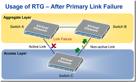
Figure 2 illustrates how the redundant trunk link topology works when the primary link goes down.

Figure 2: Redundant Trunk Group, Link 2 Active

Image g020017.gif

Link 1 is down between Switch 3 and Switch 1. Link 2 takes over as the active link. Traffic between the access layer and the distribution layer is automatically switched to Link 2 between Switch 1 and Switch 2.

image

image

 
Leave a comment

Posted by on September 18, 2011 in Switching Layer